|
Tips for PerspectiveTools |
|
When setting the vanishing points for 2-point perspective using WildTools, I see the left and right VP's, the station point(eye) and a third, movable point that is connected by a line to the face of the "magic cube". What does this third point represent and where is it placed? I learned perspective drawing the old-fashioned way(on paper with a plan and elevation) and haven't quite figured out how best to use WildTools. Thanks for your help.
MaryBeth
|
There is universal agreement, and I don't dispute it, that this is one part of PerspectiveTools that is a little short of the ideal. PerspectiveTools has three vanishing points and three tools for setting them. For this reason, it's necessary to show the three vanishing points at all times, even though one-point perspective only uses one of the vanishing points, and two-point perspective uses only two of the three. When you write software, the worst thing you can do to a user is to do nothing. This is the reason for tool fallout, and why there are so many things built into WildTools that give you a reaction when you do things: sounds, cursor changes, etc. So it wouldn't make any sense to have a tool that could edit the vertical vanishing point and then have nothing show on the screen. I'll be the first to admit, I don't know what the answer to this is, but for now, just ignore the vanishing points that you are not using. In the future, we will have the ability to emphasize these better, with various colors instead of the black-only ghosting that we have now. Alfred Scott |
|
PerspectiveTools allows several different techniques to generate a perspective view. To those used to the old-time construction methods, it is KEY to understand that in PerspectiveTools, the Picture Plane (in plan view) and the Horizon (in elevation/perspective) are represented by the SAME line. Since you learned the old-fashioned way, PerspectiveTools is for you! Here's the short description of the "old-fashioned" method: Start your drawing by placing and rotating the plan you wish to draw to your desired angle, then locate the Station Point in plan with a marker of choice. The next step would be to draw two lines, parallel to the plan, from the Station Point to a horizontal Picture Plane line of your choice. These lines form a right angle at the Station Point and locate the Left and RIght VP's. Do these things just as you would have "in the old days" using the basic drawing tools and techniques. Now, using the VP tools, align the PerspectiveTools setup to match your established VP's and Station Point. You may now use the entire pallette of tools to create the desired view. If you use the traditional construction methods to create an appropriate "bounding box" in perspective for your plan, you may use the BlockOut tool to map your orthogonal drawing to fit the perspective. Good Luck. Phil Loheed |
|
The traditional method of layout provides a precise way to create the exact perspective view you want. However, after you have located the VP's and station point in that way, there is no need to proceed further with the tedium of traditional construction. Instead, use the BlockOut tool to create a perspective plan, and go from there... (When doing this you only need to construct a perspective "bounding box" to match one you placed around the orthogonal plan. Do this just to provide a precise 'guide' for the BlockOut tool.) Note, by-the-way, that you need to "pick up" the plan from the un-rotated drawing, not the one you rotated for set-up purposes. If you haven't followed Alfred's animated demo of the PerspectiveTools, go to www.engsw.com, click the WIldTools button, then go through the PerspectiveTools section item by item -- you'll be glad you did! Especially notice how the BlockOut tool and the Camera tool work. As you watch this sequence of animations pay attention to the rotation tools: you will see that any horizontal line or array of points can be rotated in perspective to establish vertical dimensions, or you may create perspective squares using the line extrude tool. Another approach to establishing a view is to create a perspective cube at the desired plan angle; subdivide the sides of the cube using the perspective grid tool; then use the BlockOut tool to place your plan or elevations within (or on) the cube. If you group your plan inside a square 'bounding box', you will be able to rapidly place the plan at various levels up and down until you see what you like. Look also at the SketchTools demo, and you will see that these can be used in Perspective mode for 'painterly' purposes. Phil Loheed |
|
Have you no shame? Have you no pity? Is there no limit to your mercilessness? How can you inflict such misery on poor pathetic draftsmen in our wretchedness. I finally installed WT6 and tried out the new PerspectiveTools on a real live case, and I can hardly contain myself. I simply popped in the image from a jpg my client sent, established two lines per vanishing point, followed the handy-dandy instructions and in 10 minutes I had the little image before you. This is just astonishing. I think I nearly lost it when dragging out the arc that defines the tank portion on the left. You have outdone yourself. I hope you're taking your medication so you will last long enough to keep it coming. We luvs yo. Princess Emma sends her regards; when Daddy's happy, everybody's happy. Mark Walker Rhodes [Sorry, we can't show you Mark's drawings because they are for patent applications that have not been filed yet. But it's a nice perspective drawing of a machine that looks like a washing machine designed by a moron.] |
|
The WildTools perspective tools are fantastic. Now that I see how well they work, I wonder if I might be able to put elevations and plans that are not PowerCADD files into PowerCADD and then, using the Block out tool, put them into perspective. I haven't been successful with translating them into bitmaps and using the Blockout tool. Would I need to re-draw these files or, is there a way to import them into PowerCADD? Most of the plan and elevations are TIFF files. Thanks, MaryBeth |
|
Thanks for the nice words. At the time you wrote this, PerspectiveTools did not handle bitmaps, but now with WildTools 7, you can easily do anything to a bitmap that you can do to any vector object. Alfred |
|
~ ~ S T R A N G E I N T E R L U D E ~ ~ Three-point perspective uses all three vanishing points. You may use these tools to set the vanishing points at any time, and you may set any of the three vanishing points, even if you are not using them in the current perspective drawing mode. In other words, you may set the Bottom Vanishing Point, even if you are in one-point perspective mode, which does not use that vanishing point. The vanishing points are stored in your drawing and they may be off the page. To set a vanishing point, select the appropriate vanishing point tool: (1) Click on a line and drag to a second line to set the vanishing point at the intersection of the two lines. This action is identical to the WildTools Trim tool or the Intersection Points tool. --or-- (2) Hold down the Option key and click on a line or point with the Picklefork cursor. If you click on a line, the starting point of the line will be used for the vanishing point. This is to make it possible to leave lines in the drawing which extend from a vanishing point, which may be off-page. --or-- (3) Move the cursor over an existing vanishing point, click and drag the vanishing point to a new location. You may move any of the vanishing points with any of the three tools. In three-point perspectives, the vertical vanishing point is constrained to a move that is perpendicular from the horizon, however you may press the Shift key to move the vertical vanishing point left or right. Once you have selected the vanishing points, and set the tools to one-, two-, or three-point perspective drawing, you may use any of the tools to draw in perspective. Because of the nature of perspective drawings, you cannot tab into the Edit Window with these tools, and advanced snapping (perpendicular and tangent) are not provided. Now I can sleep. |
|
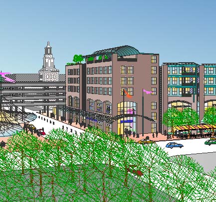
Carlos Diniz
No discussion of PerspectiveTools is complete without some mention of Carlos Diniz, a legendary character in the Los Angeles architecture scene. He was an architectural delineator, who hired Frank Gehry as a young man. He was fanatic about perspective accuracy. He created many perspectives, posters and other graphics for Phil Loheed, who worked with Carlos off and on for thirty years -- learning a lot about perspectives. Carlos was famous for his temper tantrums, but everyone loved him anyway. His final drawings were exclusively inked by hand on paper, although his block-outs were often computerized. The example above is from Architectural Rendering Techniques: A Color Reference by Mike W. Lin. Search Amazon.com for Carlos Diniz and you will find plenty of examples of his work. When Phil Loheed and I were working on PerspectiveTools, Phil kept Carlos up to date on what we were doing and both were very excited about all of this. One day in August of 2001 I called Phil, and he was crying. It isn't often you hear a grown man cry, but Phil had just learned from Ian Espinoza, Carlos' son, that Carlos had died. Ian carries on Carlos' work as IAN ESPINOZA ASSOCIATES in Burbank. Carlos Diniz is the patron saint of PerspectiveTools, and I have no doubt that we would have achieved this without all of the things Phil learned from Carlos. Alfred Scott |
|
Phil, I was talking to Alfred about how to set up and draw in perspective, I was trying to establish a scale point, just as if you were doing this manually. He told me that you use PowerCADD and were instrumental in the process of developing PerspectiveTools, and that you set up your perspective drawing using the same method as if you were drawing by hand. Placing your floor or site plan at the desired angle, setting the picture plain, and station point, projecting out to the picture plain to set vanishing points, and then vertically down to a horizon line. Then using those points set the vanishing points in PerspectiveTools, etc. Is this the best way to do a drawing in perspective? We talked further and it turns out we have a mutual acquaintance, Carlos Diniz. I used to have my office in the Granada Building when Carlos was there, and learned to do perspectives from someone who worked for him in the late sixties and early seventies (H. Richard Johnson). Robert Friedman Robert, Carlos and his first wife Sundae were old and very dear friends. He was an utterly unique man. We first met in about 1974, while working on the design of Faneuil Hall Marketplace. Over the years, we worked together on many projects literally around the world. I learned a great deal about the joys of life -- and even a thing or three about perspectives and illustration... I miss him a lot. FIRST METHOD: SECOND METHOD: -- OR -- (pregnant pause)... You may map the plan onto the bottom of the "reference cube" and elevations to the 'far sides' of the cube -- then construct your view by projecting into the space defined by the reference cube. Such projection is easily done using the Perspective Line tool (and the soon to be released Cross Plane Move capability -- see NewTools in the WildTools ThinkTank -- will allow you to duplicate and/or drag planar elements off the cube and into the scene as desired). For example, you could place a contour plan with Block Out tool, then drag each contour "up or down" to its correct location. Similarly, you could place an elevation drawing with Block Out, then drag the window frames "in or out" to recess them or create bay windows. It is helpful to maintain correct alignment to the "reference cube" with the Block Out Tool to first draw the "reference cube" orthogonally around the plan and elevations, then use the so-called 3-Point drawing mode of the Block Out tool (This allows you to trace one side of the reference cube with the Block Out, then drag toward a third corner to establish the direction of the mapping -- giving a precise alignment between perspective plans and elevations. HYBRID METHOD: THIRD METHOD: Using this third method, you can also "extract" precise elevations by tracing the photo, then thoughtfully use the Perspective Camera Tool to remap the perspective elevation to orthogonal mode. (In doing this sort of thing, the Cross Plane Move capability is extremely helpful when used to drag recessed or projected details into "plane" prior to "extraction" with the Perspective Camera Tool!!) I mention this because I am doing this sort of extraction as we speak... Hope the above is helpful. To get the hang of PerspectiveTools, try creating a few simple "primitive house" drawings using each of the methods. Also be sure to look at the online animations of the basic tool operations. Phil Loheed |
![]()